Measuring Resonances
Klipper has built-in support for ADXL345 accelerometer, which can be used to measure resonance frequencies of the printer for different axes, and auto-tune input shapers to compensate for resonances. Note that using ADXL345 requires some soldering and crimping. ADXL345 can be connected to a Raspberry Pi directly, or to an SPI interface of an MCU board (it needs to be reasonably fast).
When sourcing ADLX345, be aware that there is a variety of different PCB board designs and different clones of them. Make sure that the board supports SPI mode (small number of boards appear to be hard-configured for I2C by pulling SDO to GND), and, if it is going to be connected to a 5V printer MCU, that it has a voltage regulator and a level shifter.
Installation instructions
Wiring
You need to connect ADXL345 to your Raspberry Pi via SPI. Note that the I2C connection, which is suggested by ADXL345 documentation, has too low throughput and will not work. The recommended connection scheme:
| ADXL345 pin | RPi pin | RPi pin name |
|---|---|---|
| 3V3 (or VCC) | 01 | 3.3v DC power |
| GND | 06 | Ground |
| CS | 24 | GPIO08 (SPI0_CE0_N) |
| SDO | 21 | GPIO09 (SPI0_MISO) |
| SDA | 19 | GPIO10 (SPI0_MOSI) |
| SCL | 23 | GPIO11 (SPI0_SCLK) |
Fritzing wiring diagrams for some of the ADXL345 boards:
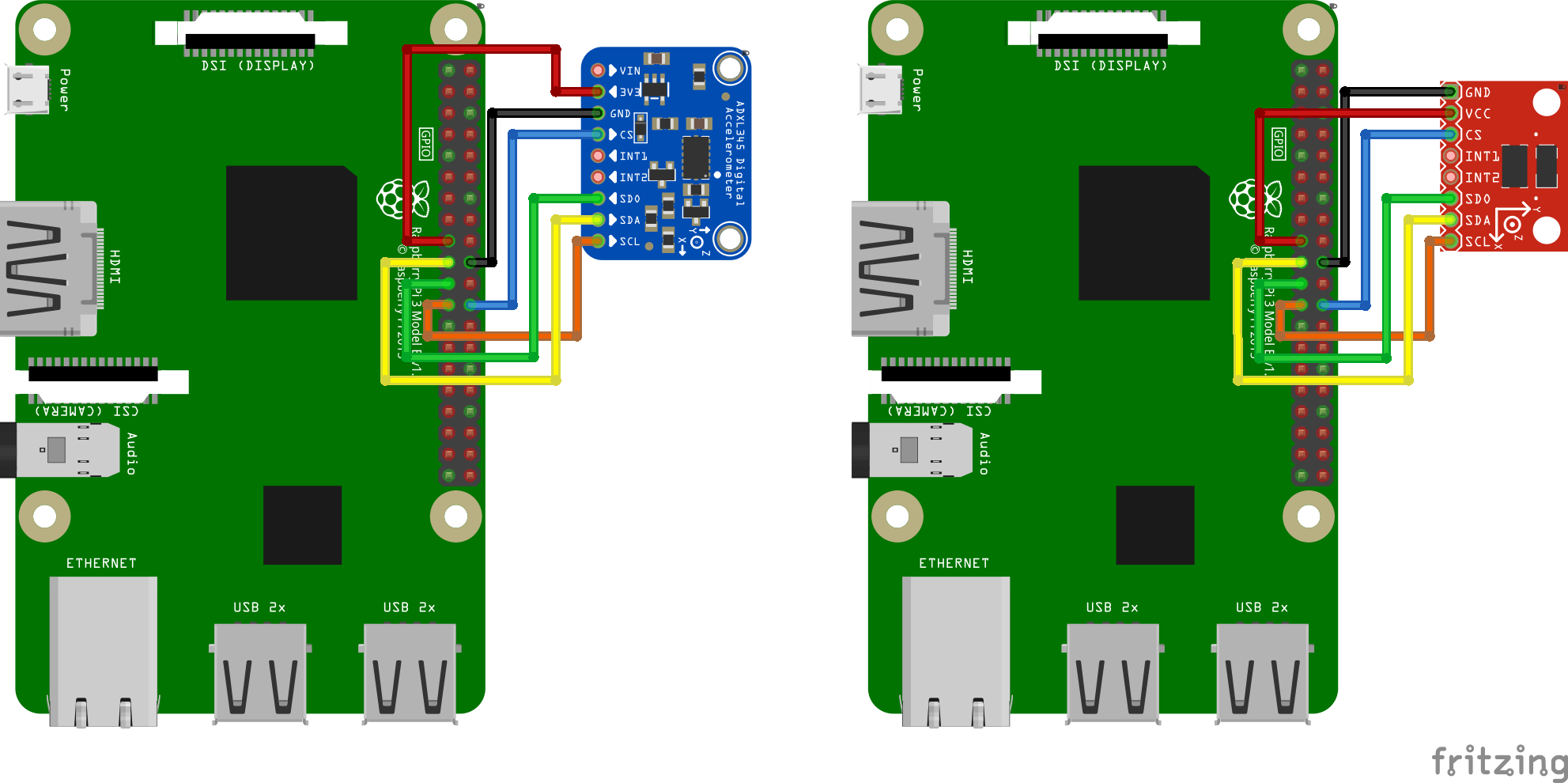
Double-check your wiring before powering up the Raspberry Pi to prevent damaging it or the accelerometer.
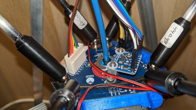
Mounting the accelerometer
The accelerometer must be attached to the toolhead. One needs to design a proper mount that fits their own 3D printer. It is better to align the axes of the accelerometer with the printer's axes (but if it makes it more convenient, axes can be swapped - i.e. no need to align X axis with X and so forth - it should be fine even if Z axis of accelerometer is X axis of the printer, etc.).
An example of mounting ADXL345 on the SmartEffector:
Note that on a bed slinger printer one must design 2 mounts: one for the toolhead and one for the bed, and run the measurements twice. See the corresponding section for more details.
Attention: make sure the accelerometer and any screws that hold it in place do not touch any metal parts of the printer. Basically, the mount must be designed such as to ensure the electrical isolation of the accelerometer from the printer frame. Failing to ensure that can create a ground loop in the system that may damage the electronics.
Software installation
Note that resonance measurements and shaper auto-calibration require additional software dependencies not installed by default. First, you will have to run on your Raspberry Pi the following command:
~/klippy-env/bin/pip install -v numpy
to install numpy package. Note that, depending on the performance of the
CPU, it may take a lot of time, up to 10-20 minutes. Be patient and wait
for the completion of the installation. On some occasions, if the board has
too little RAM, the installation may fail and you will need to enable swap.
Next, run the following commands to install the additional dependencies:
sudo apt update
sudo apt install python-numpy python-matplotlib
Afterwards, check and follow the instructions in the RPi Microcontroller document to setup the "linux mcu" on the Raspberry Pi.
Make sure the Linux SPI driver is enabled by running sudo
raspi-config and enabling SPI under the "Interfacing options" menu.
Add the following to the printer.cfg file:
[mcu rpi]
serial: /tmp/klipper_host_mcu

[adxl345]
cs_pin: rpi:None

[resonance_tester]
accel_chip: adxl345
probe_points:
    100,100,20  # an example
It is advised to start with 1 probe point, in the middle of the print bed, slightly above it.
Restart Klipper via the RESTART command.
Measuring the resonances
Checking the setup
Now you can test a connection.
- For "non bed-slingers" (e.g. one accelerometer), in Octoprint,
enter
ACCELEROMETER_QUERY - For "bed-slingers" (e.g. more than one accelerometer), enter
ACCELEROMETER_QUERY CHIP=<chip>where<chip>is the name of the chip as-entered, e.g.CHIP=bed(see: bed-slinger) for all installed accelerometer chips.
You should see the current measurements from the accelerometer, including the free-fall acceleration, e.g.
Recv: // adxl345 values (x, y, z): 470.719200, 941.438400, 9728.196800
If you get an error like Invalid adxl345 id (got xx vs e5), where xx
is some other ID, it is indicative of the connection problem with ADXL345,
or the faulty sensor. Double-check the power, the wiring (that it matches
the schematics, no wire is broken or loose, etc.), and soldering quality.
Next, try running MEASURE_AXES_NOISE in Octoprint, you should get some
baseline numbers for the noise of accelerometer on the axes (should be
somewhere in the range of ~1-100). Too high axes noise (e.g. 1000 and more)
can be indicative of the sensor issues, problems with its power, or too
noisy imbalanced fans on a 3D printer.
Measuring the resonances
Now you can run some real-life tests. Run the following command:
TEST_RESONANCES AXIS=X
Note that it will create vibrations on X axis. It will also disable input shaping if it was enabled previously, as it is not valid to run the resonance testing with the input shaper enabled.
Attention! Be sure to observe the printer for the first time, to make sure
the vibrations do not become too violent (M112 command can be used to abort
the test in case of emergency; hopefully it will not come to this though).
If the vibrations do get too strong, you can attempt to specify a lower than the
default value for accel_per_hz parameter in [resonance_tester] section, e.g.
[resonance_tester]
accel_chip: adxl345
accel_per_hz: 50  # default is 75
probe_points: ...
If it works for X axis, run for Y axis as well:
TEST_RESONANCES AXIS=Y
This will generate 2 CSV files (/tmp/resonances_x_*.csv and
/tmp/resonances_y_*.csv). These files can be processed with the stand-alone
script on a Raspberry Pi. To do that, run running the following commands:
~/klipper/scripts/calibrate_shaper.py /tmp/resonances_x_*.csv -o /tmp/shaper_calibrate_x.png
~/klipper/scripts/calibrate_shaper.py /tmp/resonances_y_*.csv -o /tmp/shaper_calibrate_y.png
This script will generate the charts /tmp/shaper_calibrate_x.png and
/tmp/shaper_calibrate_y.png with frequency responses. You will also get the
suggested frequencies for each input shaper, as well as which input shaper is
recommended for your setup. For example:
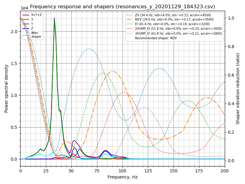
Fitted shaper 'zv' frequency = 34.4 Hz (vibrations = 4.0%, smoothing ~= 0.132)
To avoid too much smoothing with 'zv', suggested max_accel <= 4500 mm/sec^2
Fitted shaper 'mzv' frequency = 34.6 Hz (vibrations = 0.0%, smoothing ~= 0.170)
To avoid too much smoothing with 'mzv', suggested max_accel <= 3500 mm/sec^2
Fitted shaper 'ei' frequency = 41.4 Hz (vibrations = 0.0%, smoothing ~= 0.188)
To avoid too much smoothing with 'ei', suggested max_accel <= 3200 mm/sec^2
Fitted shaper '2hump_ei' frequency = 51.8 Hz (vibrations = 0.0%, smoothing ~= 0.201)
To avoid too much smoothing with '2hump_ei', suggested max_accel <= 3000 mm/sec^2
Fitted shaper '3hump_ei' frequency = 61.8 Hz (vibrations = 0.0%, smoothing ~= 0.215)
To avoid too much smoothing with '3hump_ei', suggested max_accel <= 2800 mm/sec^2
Recommended shaper is mzv @ 34.6 Hz
The suggested configuration can be added to [input_shaper] section of
printer.cfg, e.g.:
[input_shaper]
shaper_freq_x: ...
shaper_type_x: ...
shaper_freq_y: 34.6
shaper_type_y: mzv

[printer]
max_accel: 3000  # should not exceed the estimated max_accel for X and Y axes
or you can choose some other configuration yourself based on the generated charts: peaks in the power spectral density on the charts correspond to the resonance frequencies of the printer.
Note that alternatively you can run the input shaper autocalibration from Klipper directly, which can be convenient, for example, for the input shaper re-calibration.
Bed-slinger printers
If your printer is a bed slinger printer, you will need to change the location of the accelerometer between the measurements for X and Y axes: measure the resonances of X axis with the accelerometer attached to the toolhead and the resonances of Y axis - to the bed (the usual bed slinger setup).
However, you can also connect two accelerometers simultaneously, though they must be connected to different boards (say, to an RPi and printer MCU board), or to two different physical SPI interfaces on the same board (rarely available). Then they can be configured in the following manner:
[adxl345 hotend]
# Assuming `hotend` chip is connected to an RPi
cs_pin: rpi:None

[adxl345 bed]
# Assuming `bed` chip is connected to a printer MCU board
cs_pin: ...  # Printer board SPI chip select (CS) pin

[resonance_tester]
# Assuming the typical setup of the bed slinger printer
accel_chip_x: adxl345 hotend
accel_chip_y: adxl345 bed
probe_points: ...
Then the commands TEST_RESONANCES AXIS=X and TEST_RESONANCES AXIS=Y
will use the correct accelerometer for each axis.
Max smoothing
Keep in mind that the input shaper can create some smoothing in parts.
Automatic tuning of the input shaper performed by calibrate_shaper.py
script or SHAPER_CALIBRATE command tries not to exacerbate the smoothing,
but at the same time they try to minimize the resulting vibrations.
Sometimes they can make a sub-optimal choice of the shaper frequency, or
maybe you simply prefer to have less smoothing in parts at the expense of
a larger remaining vibrations. In these cases, you can request to limit
the maximum smoothing from the input shaper.
Let's consider the following results from the automatic tuning:
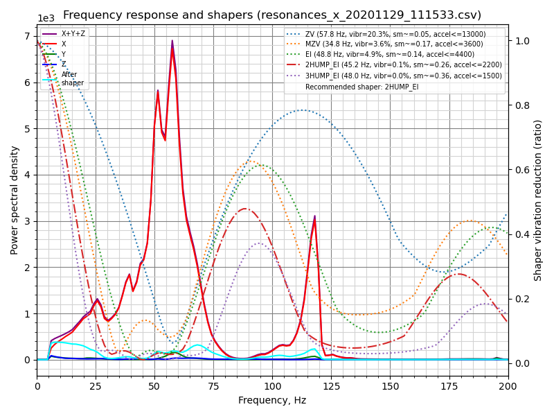
Fitted shaper 'zv' frequency = 57.8 Hz (vibrations = 20.3%, smoothing ~= 0.053)
To avoid too much smoothing with 'zv', suggested max_accel <= 13000 mm/sec^2
Fitted shaper 'mzv' frequency = 34.8 Hz (vibrations = 3.6%, smoothing ~= 0.168)
To avoid too much smoothing with 'mzv', suggested max_accel <= 3600 mm/sec^2
Fitted shaper 'ei' frequency = 48.8 Hz (vibrations = 4.9%, smoothing ~= 0.135)
To avoid too much smoothing with 'ei', suggested max_accel <= 4400 mm/sec^2
Fitted shaper '2hump_ei' frequency = 45.2 Hz (vibrations = 0.1%, smoothing ~= 0.264)
To avoid too much smoothing with '2hump_ei', suggested max_accel <= 2200 mm/sec^2
Fitted shaper '3hump_ei' frequency = 48.0 Hz (vibrations = 0.0%, smoothing ~= 0.356)
To avoid too much smoothing with '3hump_ei', suggested max_accel <= 1500 mm/sec^2
Recommended shaper is 2hump_ei @ 45.2 Hz
Note that the reported smoothing values are some abstract projected values.
These values can be used to compare different configurations: the higher the
value, the more smoothing a shaper will create. However, these smoothing scores
do not represent any real measure of smoothing, because the actual smoothing
depends on max_accel and square_corner_velocity
parameters. Therefore, you should print some test prints to see how much
smoothing exactly a chosen configuration creates.
In the example above the suggested shaper parameters are not bad, but what if you want to get less smoothing on the X axis? You can try to limit the maximum shaper smoothing using the following command:
~/klipper/scripts/calibrate_shaper.py /tmp/resonances_x_*.csv -o /tmp/shaper_calibrate_x.png --max_smoothing=0.2
which limits the smoothing to 0.2 score. Now you can get the following result:
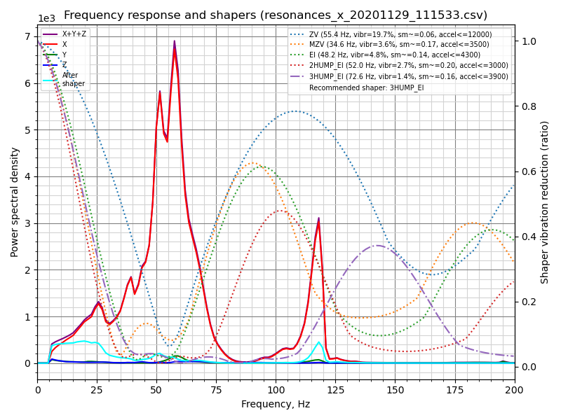
Fitted shaper 'zv' frequency = 55.4 Hz (vibrations = 19.7%, smoothing ~= 0.057)
To avoid too much smoothing with 'zv', suggested max_accel <= 12000 mm/sec^2
Fitted shaper 'mzv' frequency = 34.6 Hz (vibrations = 3.6%, smoothing ~= 0.170)
To avoid too much smoothing with 'mzv', suggested max_accel <= 3500 mm/sec^2
Fitted shaper 'ei' frequency = 48.2 Hz (vibrations = 4.8%, smoothing ~= 0.139)
To avoid too much smoothing with 'ei', suggested max_accel <= 4300 mm/sec^2
Fitted shaper '2hump_ei' frequency = 52.0 Hz (vibrations = 2.7%, smoothing ~= 0.200)
To avoid too much smoothing with '2hump_ei', suggested max_accel <= 3000 mm/sec^2
Fitted shaper '3hump_ei' frequency = 72.6 Hz (vibrations = 1.4%, smoothing ~= 0.155)
To avoid too much smoothing with '3hump_ei', suggested max_accel <= 3900 mm/sec^2
Recommended shaper is 3hump_ei @ 72.6 Hz
If you compare to the previously suggested parameters, the vibrations are a bit larger, but the smoothing is significantly smaller than previously, allowing larger maximum acceleration.
When deciding which max_smoothing parameter to choose, you can use a
trial-and-error approach. Try a few different values and see which results
you get. Note that the actual smoothing produced by the input shaper depends,
primarily, on the lowest resonance frequency of the printer: the higher
the frequency of the lowest resonance - the smaller the smoothing. Therefore,
if you request the script to find a configuration of the input shaper with the
unrealistically small smoothing, it will be at the expense of increased ringing
at the lowest resonance frequencies (which are, typically, also more prominently
visible in prints). So, always double-check the projected remaining vibrations
reported by the script and make sure they are not too high.
Note that if you chose a good max_smoothing value for both of your axes, you
can store it in the printer.cfg as
[resonance_tester]
accel_chip: ...
probe_points: ...
max_smoothing: 0.25  # an example
Then, if you rerun the input shaper auto-tuning
using SHAPER_CALIBRATE Klipper command in the future, it will use the stored
max_smoothing value as a reference.
Selecting max_accel
Since the input shaper can create some smoothing in parts, especially at high
accelerations, you will still need to choose the max_accel value that
does not create too much smoothing in the printed parts. A calibration script
provides an estimate for max_accel parameter that should not create too much
smoothing. Note that the max_accel as displayed by the calibration script is
only a theoretical maximum at which the respective shaper is still able to work
without producing too much smoothing. It is by no means a recommendation to set
this acceleration for printing. The maximum acceleration your printer is able to
sustain depends on its mechanical properties and the maximum torque of the used
stepper motors. Therefore, it is suggested to set max_accel in [printer]
section that does not exceed the estimated values for X and Y axes, likely with
some conservative safety margin.
Alternatively, follow
this part of
the input shaper tuning guide and print the test model to choose max_accel
parameter experimentally.
The same notice applies to the input shaper
auto-calibration with
SHAPER_CALIBRATE command: it is still necessary to choose the right
max_accel value after the auto-calibration, and the suggested acceleration
limits will not be applied automatically.
If you are doing a shaper re-calibration and the reported smoothing for the suggested shaper configuration is almost the same as what you got during the previous calibration, this step can be skipped.
Testing custom axes
TEST_RESONANCES command supports custom axes. While this is not really
useful for input shaper calibration, it can be used to study printer
resonances in-depth and to check, for example, belt tension.
To check the belt tension on CoreXY printers, execute
TEST_RESONANCES AXIS=1,1 OUTPUT=raw_data
TEST_RESONANCES AXIS=1,-1 OUTPUT=raw_data
and use graph_accelerometer.py to process the generated files, e.g.
~/klipper/scripts/graph_accelerometer.py -c /tmp/raw_data_axis*.csv -o /tmp/resonances.png
which will generate /tmp/resonances.png comparing the resonances.
For Delta printers with the default tower placement (tower A ~= 210 degrees, B ~= 330 degrees, and C ~= 90 degrees), execute
TEST_RESONANCES AXIS=0,1 OUTPUT=raw_data
TEST_RESONANCES AXIS=-0.866025404,-0.5 OUTPUT=raw_data
TEST_RESONANCES AXIS=0.866025404,-0.5 OUTPUT=raw_data
and then use the same command
~/klipper/scripts/graph_accelerometer.py -c /tmp/raw_data_axis*.csv -o /tmp/resonances.png
to generate /tmp/resonances.png comparing the resonances.
Input Shaper auto-calibration
Besides manually choosing the appropriate parameters for the input shaper feature, it is also possible to run the auto-tuning for the input shaper directly from Klipper. Run the following command via Octoprint terminal:
SHAPER_CALIBRATE
This will run the full test for both axes and generate the csv output
(/tmp/calibration_data_*.csv by default) for the frequency response
and the suggested input shapers. You will also get the suggested
frequencies for each input shaper, as well as which input shaper is
recommended for your setup, on Octoprint console. For example:
Calculating the best input shaper parameters for y axis
Fitted shaper 'zv' frequency = 39.0 Hz (vibrations = 13.2%, smoothing ~= 0.105)
To avoid too much smoothing with 'zv', suggested max_accel <= 5900 mm/sec^2
Fitted shaper 'mzv' frequency = 36.8 Hz (vibrations = 1.7%, smoothing ~= 0.150)
To avoid too much smoothing with 'mzv', suggested max_accel <= 4000 mm/sec^2
Fitted shaper 'ei' frequency = 36.6 Hz (vibrations = 2.2%, smoothing ~= 0.240)
To avoid too much smoothing with 'ei', suggested max_accel <= 2500 mm/sec^2
Fitted shaper '2hump_ei' frequency = 48.0 Hz (vibrations = 0.0%, smoothing ~= 0.234)
To avoid too much smoothing with '2hump_ei', suggested max_accel <= 2500 mm/sec^2
Fitted shaper '3hump_ei' frequency = 59.0 Hz (vibrations = 0.0%, smoothing ~= 0.235)
To avoid too much smoothing with '3hump_ei', suggested max_accel <= 2500 mm/sec^2
Recommended shaper_type_y = mzv, shaper_freq_y = 36.8 Hz
If you agree with the suggested parameters, you can execute SAVE_CONFIG
now to save them and restart the Klipper. Note that this will not update
max_accel value in [printer] section. You should update it manually
following the considerations in Selecting max_accel
section.
If your printer is a bed slinger printer, you can specify which axis to test, so that you can change the accelerometer mounting point between the tests (by default the test is performed for both axes):
SHAPER_CALIBRATE AXIS=Y
You can execute SAVE_CONFIG twice - after calibrating each axis.
However, if you connected two accelerometers simultaneously, you simply run
SHAPER_CALIBRATE without specifying an axis to calibrate the input shaper
for both axes in one go.
Input Shaper re-calibration
SHAPER_CALIBRATE command can be also used to re-calibrate the input shaper in
the future, especially if some changes to the printer that can affect its
kinematics are made. One can either re-run the full calibration using
SHAPER_CALIBRATE command, or restrict the auto-calibration to a single axis by
supplying AXIS= parameter, like
SHAPER_CALIBRATE AXIS=X
Warning! It is not advisable to run the shaper autocalibration very frequently (e.g. before every print, or every day). In order to determine resonance frequencies, autocalibration creates intensive vibrations on each of the axes. Generally, 3D printers are not designed to withstand a prolonged exposure to vibrations near the resonance frequencies. Doing so may increase wear of the printer components and reduce their lifespan. There is also an increased risk of some parts unscrewing or becoming loose. Always check that all parts of the printer (including the ones that may normally not move) are securely fixed in place after each auto-tuning.
Also, due to some noise in measurements, it is possible that the tuning results will be slightly different from one calibration run to another one. Still, it is not expected that the noise will affect the print quality too much. However, it is still advised to double-check the suggested parameters, and print some test prints before using them to confirm they are good.
Offline processing of the accelerometer data
It is possible to generate the raw accelerometer data and process it offline (e.g. on a host machine), for example to find resonances. In order to do so, run the following commands via Octoprint terminal:
SET_INPUT_SHAPER SHAPER_FREQ_X=0 SHAPER_FREQ_Y=0
TEST_RESONANCES AXIS=X OUTPUT=raw_data
ignoring any errors for SET_INPUT_SHAPER command. For TEST_RESONANCES
command, specify the desired test axis. The raw data will be written into
/tmp directory on the RPi.
The raw data can also be obtained by running the command ACCELEROMETER_MEASURE
command twice during some normal printer activity - first to start the
measurements, and then to stop them and write the output file. Refer to
G-Codes for more details.
The data can be processed later by the following scripts:
scripts/graph_accelerometer.py and scripts/calibrate_shaper.py. Both
of them accept one or several raw csv files as the input depending on the
mode. The graph_accelerometer.py script supports several modes of operation:
- plotting raw accelerometer data (use
-rparameter), only 1 input is supported; - plotting a frequency response (no extra parameters required), if multiple inputs are specified, the average frequency response is computed;
- comparison of the frequency response between several inputs (use
-cparameter); you can additionally specify which accelerometer axis to consider via-a x,-a yor-a zparameter (if none specified, the sum of vibrations for all axes is used); - plotting the spectrogram (use
-sparameter), only 1 input is supported; you can additionally specify which accelerometer axis to consider via-a x,-a yor-a zparameter (if none specified, the sum of vibrations for all axes is used).
Note that graph_accelerometer.py script supports only the raw_data*.csv files and not resonances*.csv or calibration_data*.csv files.
For example,
~/klipper/scripts/graph_accelerometer.py /tmp/raw_data_x_*.csv -o /tmp/resonances_x.png -c -a z
will plot the comparison of several /tmp/raw_data_x_*.csv files for Z axis to
/tmp/resonances_x.png file.
The shaper_calibrate.py script accepts 1 or several inputs and can run automatic
tuning of the input shaper and suggest the best parameters that work well for
all provided inputs. It prints the suggested parameters to the console, and can
additionally generate the chart if -o output.png parameter is provided, or
the CSV file if -c output.csv parameter is specified.
Providing several inputs to shaper_calibrate.py script can be useful if running some advanced tuning of the input shapers, for example:
- Running
TEST_RESONANCES AXIS=X OUTPUT=raw_data(andYaxis) for a single axis twice on a bed slinger printer with the accelerometer attached to the toolhead the first time, and the accelerometer attached to the bed the second time in order to detect axes cross-resonances and attempt to cancel them with input shapers. - Running
TEST_RESONANCES AXIS=Y OUTPUT=raw_datatwice on a bed slinger with a glass bed and a magnetic surfaces (which is lighter) to find the input shaper parameters that work well for any print surface configuration. - Combining the resonance data from multiple test points.
- Combining the resonance data from 2 axis (e.g. on a bed slinger printer to configure X-axis input_shaper from both X and Y axes resonances to cancel vibrations of the bed in case the nozzle 'catches' a print when moving in X axis direction).